Technical Support - Gas Cooler Finder
Hints for Program Use
In this help file general hints and selection criteria are explained which are common to all cooler selections. This includes hints for gas parameters, heat exchangers and gas coolers as well as hints what to do if the selected heat exchanger would be overdriven.
This programme calculates the coolers matching you application. You fill in the parameters requested. The coolers that are shown in the resulting table are able to fulfil the needs in general. On the other hand not all of the coolers or heat exchangers do make sense (see e.g. explanations in chapter 3.3).
On more hint concerning the program use: parameters can only be filled in for one gas path. If you have got more than one gas path, fill in the parameters of the stream with the highest gas energy.
1. Gas parameters
2. Heat exchangers
2.1 Material selection
2.2 Characteristics of heat exchangers / Selection hints
2.3 Double stream exchangers
2.4 Heat exchanger type 2
2.5 What to do in case of heat exchanger overdrive ?
3. Gaskühler
3.1 Peltier gas coolers
3.2 Compressor gas coolers
3.3 Hints to result-list
3.4 Mounting instructions
3.5 What to do in case of cooler overdrive ?
4. Accessories
1. Gas parameters
The calculations are based on cooling of air-like gases, which is sufficient in most cases of sample gas analysis.
a) (Maximum) inlet gas temperature:
This is the temperature of the gas to be cooled at the heat exchanger inlet. The hotter the gas, the more cooling energy has to be served. Depending on the heat exchanger there is an upper limit for the inlet temperature (steel: 180°C/356°F; glass and PVDF 140°C/284°F).
b) Maximum inlet gas temperature / moisture content:
- Maximum inlet gas temperature:
This describes the amount of vapour content in the gas to be cooled. If the gas temperature drops below the dew point temperature, the water begins to condense (therefore the dew point is always lower than the inlet temperature). As a rule you can say that energy to cool the gas about doubles with a rise of dew point of 10°C/18°F. It is obvious, that the maximum dew point has to be set very careful for your application. The upper limit of dew point is set by the heat exchangers specification. A dew point below 6°C does not make sense which sets the lower limit. - Moisture content:
A better description of the vapour content of the gas is volume percent. Since the dew point depends on pressure, giving the volume percentage avoids from getting pressure influences. The moisture content of gas is an important factor for the cooler configuration. The higher this content, the more cooling capacity is required. The maximal moisture content is determined by the gas inlet temperature. In this case the maximum gas inlet dew point corresponds with the gas inlet temperature.
c) The output dew point:
The output dew point is the temperature setting to which the sample gas must be cooled so the specific moisture can condense. This temperature can be set on the cooler based on the dew point of the sample gas. An output dew point higher than the standard 5°C/41°F for steady input dew point will result in a lower gas rate for the cooler to cool. A similar logic applies to the function of the Delta-T control. For more details, please refer to chapter Peltier Coolers.
d) Gas pressure p:
The gas pressure affects the density of the gas. As a rule: double pressure = double energy to cool (with same volume). Inside the range of about 0.5 to 3 bar (7 to 43 psi) we abstract from a dew points pressure variation with sufficient accuracy. The pressure for glass and PVDF heat exchangers is limited.
e) Volume flow per gas path Q::
Measured in l/h (l/min) of cooled air which means downstream of the cooler. The relation of flow and energy is linear. If you want to set the flow in standard liter / h (standard l/min) you have to set the pressure to 1bar/14.5psi.
f) Relative Moisture (calculated magnitude):
The relative moisture of the gas is normally not a speaking parameter. Relative moisture (humidity) tells the rate of the moisture capacity at the given inlet temperature. Indirectly it indicates the overheating of the gas above the dew point.
2. Heat exchangers
Heat exchangers have large influence on the capacity and efficiency of the cooling system. The physical dependencies are rather complicated so we are limiting the explanations to the basics. We presume the factory setting of the gas outlet temperature and dew point of approximately 5°C/41°F. The possible setting range for the cooler as well as in the calculation program is between + 2°C (35,6°F) and + 20°C (68°F) dew point.
2.1 Material selection
Cooling principles in mind, stainless steel would always be the best choice. On the other hand your gas might have aggressive components which do not allow the use of steel. You should choose glass then. PVDF heat exchangers are particularly used as their mechanical stability is higher than glass.
The offered heat exchangers you can take out of the data sheet of the current cooler, further types upon request.
2.2 Characteristics of heat exchangers / Selection hints
Efficiency of a heat exchanger depends on the design, material and the described gas parameters. The design of Buhler heat exchangers guarantees high dew point stability over a wide gas parameter range and their variation.
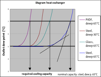
The lower the relative humidity or the moisture content of the gas, the less efficient a heat exchanger typically is. I.e. the efficiency decreases as the distance between the inlet dew point and gas inlet temperature increases. The efficiency thus also increases as the dew point increases. The chart below which qualitatively plots the output dew point / output temperature through the cooling energy is intended to illustrate this. It further shows the dependence on the volume flow.
So you can see that the maximum cooling capacity of the heat exchangers is lower when using gas with an inlet dew point of 30°C/86°F (see brown curve in the chart) than when using gas with an inlet dew point of 65°C/149°F (see blue curve in the chart). Glass and PVDF heat exchangers have a lower cooling capacity than stainless steel versions (see petrol or magenta curve in the chart).
The maximum cooling capacity of heat exchangers can be defined for applications using the three parameters gas inlet temperature, gas inlet dew point, and gas pressure. This yields the maximum flow rate of dry gas.
Note: you have to keep in mind, that the effect of input parameter changes on the outlet dew point is increasing towards the maximum cooling capacity (shown by the tangents in the diagram). We suggest to limit the load on the heat exchanger to a range of 60..80%. This rate is shown in the output sheet.
We want to add a remark about the nominal capacity of the heat exchanger. The definition should be: when the inlet parameters gas temperature, dew point and pressure are defined, then the volume flow will be increased until it rises 2°C/3.6°F above the nominal outlet dewpoint. This flow is the one you will find in the data sheets. The defined values for heat exchangers are given by "typical" applications:
Peltier cooler TC-Standard
Te = 70°C/158°F and τe = 40°C/104°F at p = 1 bar
Compressor cooler EGK
Te = 90°C/194°F and τe = 65°C/149°F at p = 1 bar
When defining the three parameters the maximum flow rate, listed in the data sheets for the heat exchangers, can then be determined.
As you can see from the above explanations, maximum flow is different with variation of the other inlet parameters. You don't have to keep this in mind, the program does it for you.
2.3 Double stream exchangers
Buehler double stream exchangers with coolers TC-MIDI, EGK 1SD, EGK 1/2 or EGK 2A Ex give you the opportunity to cool two gas streams with one heat exchanger. For example you might replace two TC-Standard one EGK 1/2 or TC-MIDI with a double stream exchanger fitted (which saves money and time for mounting).
The gas paths in dual heat exchangers are entirely separate by design.
The temperature exchange between the two gas paths in the dual heat exchanger is very low. The variance in gas energy of a gas path throughout the entire (!) output range of the heat exchanger only causes an output dew point variance of max. 0.5K in the other gas path.
Assumed that gas energies are the same on both streams, variations of the one streams outlet dewpoint by switching on and off the other stays below 0,2K/0.4°F, which is acceptable at a dew point of 5°C/41°F.
2.5 What to do in the case of heat exchanger overdrive?
The simple solution is to connect two or more heat exchangers in parallel. This option is only valid for standard heat exchangers and not for type 2. Connecting the standard heat exchangers in line does not lead to success. With the in-line connection the first heat exchanger would have to take most of the cooling while the next exchanger has to work at a low inlet dewpoint, which leads to poor efficiancy resulting in a worse dew point stability. Connecting the standard exchangers in parallel, both exchangers have the same energy to handle and they work at a lower rate of utilisation which leads to higher dew point stability.
3. Gas cooler
Bühler Technologies GmbH offers two product lines of gas coolers. They are Peltier coolers, the TC series, and compressor coolers, the EGK series. The cooling principles of both product lines share that the available cooling capacity decreases as the ambient temperature rises.
The maximum ambient temperature at the site where the coolers are installed are therefore an important boundary parameter in the configuration. The ambient temperature required by the cooler calculator is determined by the temperature of the ambient air taken in by the cooler.
The example assumes the cooler is installed inside an analysis cabinet. Here the temperature inside the cabinet is crucial, not the temperature outside the cabinet.
Please read the chapter 3.4 mounting instructions below for further instructions.
The coolers size is defined by it's nominal capacity, which should be it's capacity at a defined ambient temperature. For details please read the corresponding data sheet of the current cooler.
The results further break the coolers down into max. cooling performance and min. wash-out. The potential wash-out effects are not as important in power-optimised coolers, whereas in coolers with reduced washout special attention was paid to meeting the requirements of DIN EN 15267-3. For a low washout configuration, set the parameters “material heat exchanger” to “PVDF” or “Glass”, “Number of gas paths” to 1 and “Number of heat exchangers” to 2.
3.1 Peltier gas coolers
These coolers are very compact and designed for single gas paths, or special models for two gas paths. Heat exchangers are available in stainless steel, Duran glass and PVDF. Based on the cooling principle they are designed for moderate performance and ambient temperatures. In return they are less expensive than compressor coolers. They’re primarily used for gas flow rates of up to 150 Nl/h at gas temperatures up to 70 °C/158 °F and an inlet dew point of 40 °C/104 °F.
Peltier gas coolers have a special control unit, the so-called Delta-T control, for increased performance. Not all applications require an output dew point of 5 °C/41 °F. In some applications a higher dew point is sufficient. In other applications a stable output dew point doesn’t matter, it’s enough for the gas to be dry, so if the output dew point has an adequate difference in temperature to the ambient temperature.
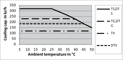
With the Delta-T control the outlet dew point is regulated by a defined value below the current ambient temperature. This extends the potential cooling capacity to the limits of the heat exchanger. Here it’s important to note the output dew point fluctuates along with the ambient temperature and a stable dew point cannot be a prerequisite for the measurement. The charts below illustrate this. The chart above shows the differences in the available cooling capacity as a function of the ambient temperature. This compares the trend of setting the dew point to 10 °C/50 °F with a 15 K or 30 K temperature difference (Delta-T). The chart below shows the different dew points this causes.

3.2 Compressor coolers
The compressor coolers of EGK type have more cooling power than peltier coolers and are designed for ambient temperatures up to 50°C/122°F. Single stream heat exchangers are available made of stainless steel, Duran glass and PVDF. Double stream exchangers are available made of stainless steel an. Duran glass. See chapter "heat exchangers" for selection.
3.3 Hints to result-list
Of course the coolers will do their job while 100 % utilized (rate of utilization is given in the output sheet of the program). But you should keep in mind that ambient temperature might sometimes have higher peaks. There may be peaks of the inlet parameters, too. You should leave a headroom of about 20% for ambient temperature peaks and dirt (explained in chapter "3.4 Mounting instructions").
3.4 Mounting instructions
As mentioned above, cooling capacity is sensitive to the temperature of the air used for cooling. Mounting must ensure that the cooler gets the lowest temperature possible (Lower limit is 5°C/41°F for all types). Check for sufficient ventilation when mounting the cooler inside a cabinet. Avoid circulation from the air outlet to the air inlet. Obstacles must be at least 10 cm (4 inches) away from the air in- and outlet. More is better, of course.
After some duty time it may occur that dust dirties the cooling air path, especially at high dust rates in air. This will reduce cooling capacity. We suggest to design the installation in a way which allows cleaning the air path with a small brush or pressurized air (be careful of rotating fans, disconnect power first).
3.5 What to do in case of cooler overdrive ?
1) Decreasing ambient temperature (e.g. by forced convection inside a cabinet) is most effective.
2) Decrease the required cooling capacity:
a) By reducing the volume to be cooled
b) By application of pre-cooling (call us)
c) By using the Delta-T-control (Peltier gas coolers only)
d) By raising the output dew point (Peltier gas coolers only)
e) by adjustment of parameters inlet gas temperature, gas inlet dew point or gas pressure
(explained in chapter 2.2 Characteristics of heat exchangers / Selection hints)
4. Accessories
For further sample gas conditioning we offer sample gas pumps to transport or moisture detectors and filters for process reliability based on the operating mode of the conditioning system. We offer automatic condensate drains or peristaltic pumps for draining condensate. These and other options can be directly integrated upon request. See the data sheets on our website of for available options.